
How does a universal tensile testing machine work?
A Universal Tensile Testing Machine (UTM) is a comprehensive testing device used to measure the mechanical properties of materials under external forces. It is widely applied in materials science, manufacturing, quality inspection, and scientific research. By applying precisely controlled loads to test specimens, the machine evaluates mechanical parameters such as tensile strength, bending performance, and compressive limits.
Although the name includes the term “tensile,” a universal tensile testing machine is capable of performing multiple fundamental mechanical tests, including tension, compression, bending, and shear. As such, it is an essential tool for evaluating the mechanical behavior of materials.
This article begins with the basic working principles of a universal tensile testing machine and then systematically explains its key components, force generation and measurement, data acquisition and analysis during testing, operational procedures, and factors affecting test results, providing a comprehensive understanding of how the machine works.
Basic Structure of a Universal Tensile Testing Machine
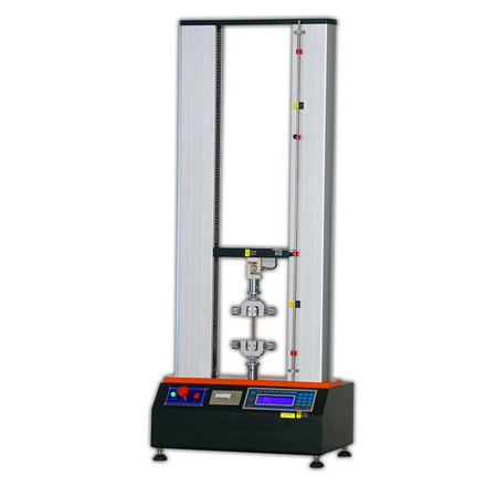
To understand how the machine operates, it is first necessary to become familiar with its main components. The core structure of a universal tensile testing machine includes the load frame, drive system, loading mechanism, sensors and measurement systems, grips (or fixtures), and the data acquisition and control system.
Load Frame
The load frame is the main structural body of the machine and is responsible for withstanding the forces generated during testing. It is typically constructed from rigid steel structures capable of withstanding forces ranging from several thousand to hundreds of thousands of newtons without significant deformation.
The load frame generally consists of two or more vertical columns and a movable crosshead, which is used to mount the test specimen and apply loads.
Crosshead: A movable component that travels vertically along the frame to apply force or displacement to the clamped specimen.
Columns: Structural members that support the entire loading system and maintain overall stability during testing.
The higher the rigidity of the load frame, the more reliable the test results will be under high-load conditions.
Drive System
The drive system is the key component responsible for generating controlled force or displacement. It is typically divided into two main types:
Electromechanical Drive: Uses an electric motor and lead screw mechanism to drive crosshead movement, enabling precise displacement control. This type is suitable for small to medium load testing and allows accurate control of speed and displacement.
Hydraulic Drive: Uses hydraulic pumps and cylinders to generate large forces, making it suitable for testing high-load materials such as metals and concrete. Hydraulic systems offer high force capacity and fast response, although their control precision is generally lower than that of servo-driven systems.
The drive system applies gradually changing force or continuous displacement to the specimen according to predefined test programs, allowing the material to undergo tensile, compressive, or other mechanical tests.
Load Cell
The load cell is one of the most critical force-measuring components in a universal testing machine. It is responsible for continuously measuring the load applied to the specimen, whether tensile or compressive.
Typically installed between the crosshead and the grips, the load cell converts mechanical force into an electrical signal, enabling precise force data acquisition throughout the test.
The accuracy of the load cell directly affects the reliability of test data. It must be regularly calibrated and properly aligned with the specimen. Common load cell accuracy levels are within ±1% or better.
Grips and Fixtures
Grips are used to securely hold the specimen so that it does not slip or experience uneven stress during testing. Depending on the type of material being tested—such as metal rods, plastic sheets, fibers, or films—different grips are used:
Wedge grips: Provide quick clamping and are suitable for a wide range of materials.
Hydraulic or pneumatic grips: Used for materials requiring high anti-slip performance.
Specialized grips: Designed for thin films, fibers, round bars, or other non-standard specimen shapes.
Proper grip selection is essential for accurate testing, as improper clamping may cause stress concentration or invalid test results.
Deformation Measurement Device (Extensometer)
In addition to force measurement, deformation or strain measurement is equally important, as it directly affects the calculation of parameters such as elastic modulus and elongation. Extensometers can be attached directly to the specimen to measure elongation, or non-contact methods such as optical, video, or laser measurement can be used.
The accuracy of the extensometer significantly influences the precision of the stress–strain curve, which serves as the foundation for mechanical property analysis.
Control System and Software
Modern universal tensile testing machines are equipped with advanced control systems and data acquisition software. These systems allow users to set loading rates, loading modes (such as constant speed or constant force), and test endpoints. The software displays load and deformation curves in real time and automatically calculates key material properties such as yield strength, tensile strength, elastic modulus, and slope values. Test reports can also be generated and exported.
Working Principle of a Universal Tensile Testing Machine
After understanding the individual components, the working principle of the machine can be explained more clearly. The basic principle of a universal tensile testing machine is to apply controlled force or displacement to a test specimen while simultaneously measuring the force and deformation, thereby determining the material’s mechanical properties.
This process involves load application, force sensing, displacement measurement, and data analysis, as described below.
Load Application
In a tensile test, the specimen is clamped between the upper and lower grips. The drive system moves the crosshead upward or downward at a controlled speed, applying tensile force to the specimen. The loading speed and rate of force increase can be set through the control system.
For brittle materials, slower loading speeds are often used to accurately capture fracture behavior, while more elastic materials may be tested at higher speeds.
In compression tests, the specimen is placed between two platens, and the crosshead moves downward to apply compressive force, allowing the material’s compressive strength to be evaluated.
Real-Time Force Measurement
As force is applied to the specimen, the load cell detects changes in load and converts the mechanical force into electrical signals transmitted to the control system. These signals are processed into readable data curves, such as load–time or load–displacement curves.
Based on feedback from the load cell, the control system can determine whether preset load values have been reached or whether the specimen has entered yielding or fracture stages, and then adjust the test accordingly.
Displacement and Deformation Measurement
Simultaneously with force measurement, extensometers or other deformation measurement devices record the specimen’s elongation or compression. By combining load and deformation data, a stress–strain curve can be generated, which is the fundamental tool for evaluating material mechanical properties.
From the stress–strain curve, the following parameters can be determined:
Elastic modulus
Yield strength
Ultimate tensile strength
Elongation at break
These parameters provide a scientific description of the material’s elasticity, plasticity, and toughness.
Data Acquisition and Analysis
During testing, the software system continuously collects force and displacement data and automatically analyzes the results after the test is completed. Typical software functions include:
Real-time display of load–deformation curves
Calculation of stress and strain based on specimen dimensions
Automatic identification of yield and fracture points
Generation of standardized test reports for saving or printing
These analysis capabilities allow operators to quickly obtain material performance indicators and conduct comparative evaluations.
Typical Operating Procedure for Tensile Testing
Understanding the working principle becomes more practical when combined with the actual testing process. The following outlines the general procedure for a tensile test.
Specimen Preparation
First, standard specimens are prepared according to relevant testing standards such as ISO, ASTM, or GB/T. Specimens are typically elongated in shape, with a narrower gauge section in the middle and sufficient gripping areas at both ends to ensure uniform stress distribution and prevent premature failure.
Specimen Installation
The specimen is securely mounted in the upper and lower grips, ensuring proper alignment with the loading direction and centered positioning. Improper installation may introduce bending stresses or slippage, adversely affecting test results.
Initial Setup and Zeroing
Before starting the test, the control system performs zero calibration of the load cell and deformation measurement devices to ensure accurate initial readings.
Load Application
The control system is activated, and the drive mechanism applies tensile or compressive force at the preset speed. Force and displacement data are continuously recorded throughout the test.
Data Recording and Test Termination
When the specimen undergoes significant permanent deformation or fracture, the test ends. The system records final data and generates the stress–strain curve along with relevant mechanical parameters.
Advantages and Applications of Universal Tensile Testing Machines
Universal tensile testing machines significantly enhance the reliability and efficiency of mechanical testing. Their main advantages include:
Versatility: Capable of tensile, compression, bending, and other mechanical tests.
High Accuracy: High-precision load cells and deformation measurement devices enable high-resolution data acquisition.
Automation: Modern machines are equipped with software-controlled testing and automated data analysis.
Wide Applicability: Suitable for testing metals, plastics, rubber, composites, and many other materials.
In material development, product quality inspection, and engineering design validation, universal tensile testing machines are indispensable tools.
A universal tensile testing machine integrates mechanical structures, precision sensors, flexible control systems, and advanced data analysis software into a powerful material testing platform. Its core principle lies in controlling load and displacement while measuring and recording the material’s response under various loading conditions to obtain key mechanical parameters. This process involves mechanical driving, force measurement, deformation measurement, data acquisition, and analysis, all of which must work together precisely to produce reliable test results.
In conclusion, the universal tensile testing machine is not only a fundamental instrument for material testing but also an essential analytical tool in modern engineering design and research. Understanding its working principles enables better experimental design, more accurate data interpretation, and continuous improvement of material and product performance.