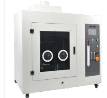
Composition of the horizontal vertical burning tester
The horizontal vertical combustion tester is a test device used to determine the flame retardancy level of equipment and apparatus components such as plastics, rubber or film, which are classified into a hierarchy of flame-retardant grades, i.e. substances with, or materials treated with, properties that significantly delay the spread of flame. Flame retardant grades for plastics are graded from HB, V-2, V-1 to V-0 in increments of.
1. HB: The lowest flame retardant grade in the UL94 standard. It requires a burning rate of less than 40 mm per minute for samples between 3 and 13 mm thick, less than 70 mm per minute for samples less than 3 mm thick, or extinguished before the 100 mm mark.
2. V-2: Flame extinguished within 60 seconds after two 10-second burn tests on samples. There may be burning material falling off.
3. V-1: Flame extinguished within 60 seconds after two 10-second flammability tests on the sample. No incendiary material can fall out.
4. V-0: Flame extinguished within 30 seconds after two 10-second flammability tests. No incendiary material can fall out.

The horizontal and vertical combustion tester is usually made up of a test section and a control section. The test part includes the burner, solenoid valve, high pressure igniter, wire specimen fixture, gas pipe, gas source, internal and external flame adjustment device, etc. The control part includes temperature measurement and control system, time measurement system and combustion control system etc. .
The combustion control system produces a flame of a certain temperature and length through the burner and other components (where the nozzle aperture of the burner should be in accordance with the test-related standards. The length of the flame produced should be in accordance with the test standard corresponding to the test sample and the flame length is measured with a flame height gauge). The flame temperature is measured and controlled by a temperature measurement system. The flame which meets the test requirements is applied to the sample mounted horizontally (vertically) on the support, the test time is measured and controlled by the time measuring system, after the specified test time is reached, the flame is separated from the test sample, the test is completed and the relevant test data is obtained.
Control method: Touch screen + PLC programming
Ignition method: automatic ignition
Test method: with transparent observation safety window, hand hole, internal lighting, top exhaust device, can be set up in the touch screen parameters, can click on the touch screen button, control panel button and remote control button three ways to test.
Flow control system: to include: solenoid valve, flow meter, pressure reducing valve, U-shaped back pressure tube (differential pressure meter) are imported original
Lamp: Benson lamp diameter 9.5mm ± 0.5mm Length from the main air inlet or entrance upwards approx. 100mm, Benson lamp mouth shape, round mouth and stainless steel fishtail-shaped mouth (replaceable)
Lamp test inclination: 0°, 20°, 45° Quick positioning, *stroke approx. 150 mm
Gas application: 98% methane (base gas), also 37MJ/m 3 ±1MJ/m 3 natural gas can be used
Application and removal time: 1s to 999.9s (touch screen presettable)
Holding time: 1s to 999.9s (touch screen presettable, automatic timing)
Number of repetitions: 1 to 9999 (touch screen presettable)
Ignition and removal time: 1s to 999.9s (touch screen presettable)
Test area volume: more than 0.75m 3 background black
Power supply power: 0.5kVA 220V 50-60Hz
Caution.
a. Check whether the liquid in the U-tube meets the requirements before turning on the gas (the liquid level should be at 0 level), if the bottom is at 0 level, please replenish the liquid, otherwise the gas will leak outwards from the U-tube.
When using different gases, the pressure of the gas will be different, thus affecting the ignition effect. In this case, the control amount of the air pressure adjustment valve under the combustion seat must be adjusted, together with the gas flow adjustment switch and the air adjustment device, in order to obtain a standard flame.
b. This equipment must be protected by a reliable electrical grounding circuit.
C. The moving part of the Bunsen burner is carried on bearings, therefore, the bearing rod must be kept clean and wiped regularly with a cloth with oil to make the bearings work properly and move freely.

